Valve adjustments to the honda engine are recommended for preventive maintenance. Below is the basic guide to adjusting your valves.
Please Note: after doing cylinder 1 you do "NOT" need to turn the crank 180 degrees to set the next cylinder and so on. Just proceed to the next cylinder number listed below.
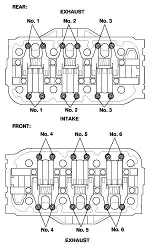
Also worth mentioning is you are going to be adjusting the intake and exhaust valves on each cylinder at the same time. Some other engine types require you to do intake on one stroke and exhaust on another stroke. The honda intake and exhaust get done at the same time. Meaning when adjusting cyl 1, do intake and exhust adjustments.
Also here is a little video online which i found that explains the process well.
NOTE: Adjust the valves only when the cylinder head temperature is less than 100 ºF (38 ºC).
Remove the cylinder head covers.
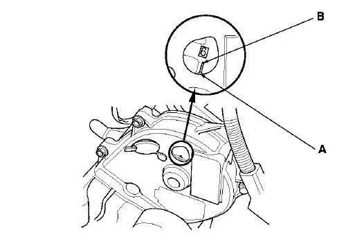
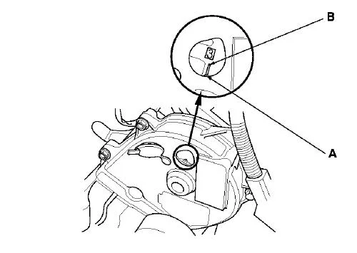
Set the No. 1 piston at top dead center (TDC).
Align the pointer (A) on the front upper cover with the No. 1 piston TDC mark (B) on the front camshaft pulley
Select the correct thickness feeler gauge for the valves you're going to check.
Valve Clearance
Intake:
0.20-0.24 mm (0.008-0.009 in.)
Exhaust:
0.28-0.32 mm (0.011-0.013 in.)
Insert the feeler gauge (A) between the adjusting screw and the end of the valve stem on No. 1 cylinder, and slide it back and forth; you should feel a slight amount of drag.

If you feel too much or too little drag, loosen the locknut (A), and turn the adjusting screw (B) until the drag on the feeler gauge is correct.
Tighten the locknut and recheck the clearance.
Repeat the adjustment, if necessary.

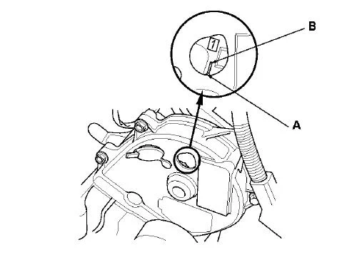
Rotate the crankshaft clockwise. Align the pointer (A) on the front upper cover with the No. 4 piston TDC mark (B) on the front camshaft pulley.
Check and, if necessary, adjust the valve clearance on No. 4 cylinder.

Rotate the crankshaft clockwise. Align the pointer (A) on the front upper cover with the No. 2 piston TDC mark (B) on the front camshaft pulley.
Check and, if necessary, adjust the valve clearance on No. 2 cylinder.
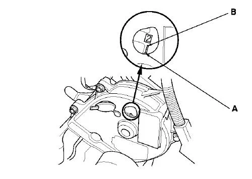
Rotate the crankshaft clockwise. Align the pointer (A) on the front upper cover with the No. 5 piston TDC mark (B) on the front camshaft pulley.
Check and, if necessary, adjust the valve clearance on No. 5 cylinder

Rotate the crankshaft clockwise. Align the pointer (A) on the front upper cover with the No. 3 piston TDC mark (B) on the front camshaft pulley.
Check and, if necessary, adjust the valve clearance on No. 3 cylinder.
Rotate the crankshaft clockwise. Align the pointer (A) on the front upper cover with the No. 6 piston TDC mark (B) on the front camshaft pulley.
Check and, if necessary, adjust the valve clearance on No. 6 cylinder.
Install the cylinder head covers.